Makes axion Views on Sheets from electrical fixtures depending on their “Room #” parameters. Tagging is optional. Makes View Set for subsequent printing.
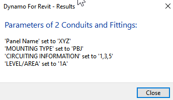
Result:

Makes axion Views on Sheets from electrical fixtures depending on their “Room #” parameters. Tagging is optional. Makes View Set for subsequent printing.
Result:
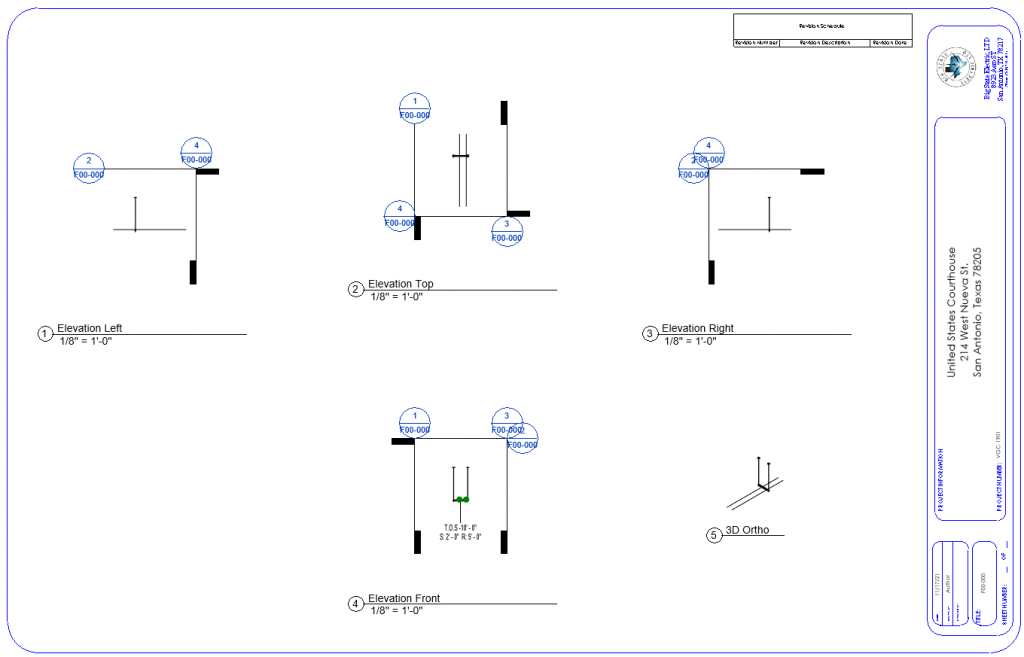
It makes the jbox Views, Sheets, puts Views on Sheets, tags the jboxes in the specified Link.
It does not yet tag conduit or deemphasize elements in the Views.
Result:
Sets parameters “BP-L”, “BP-C”, “BP-R” on brackets “RBS16” for data extracted from electrical fixtures with family name starting with “WALL”
Select which LEVEL/AREA to process in the dialog. <51-Set wall bracket parameters by nearby boxes> will attempt to do it for the whole RVT — that may take a long time.


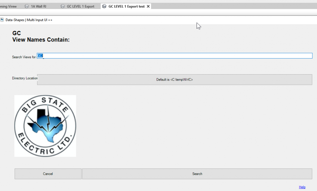
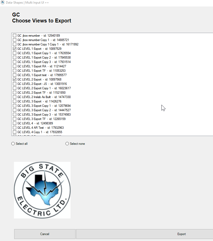
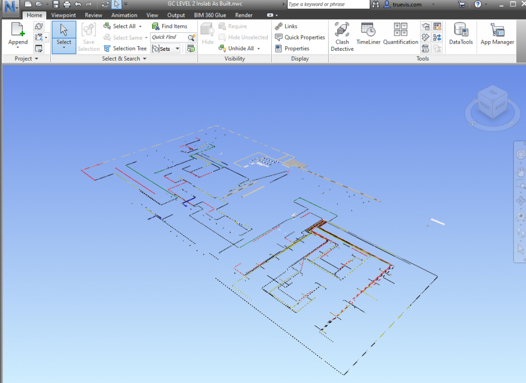
Export Views to NWC and DWG
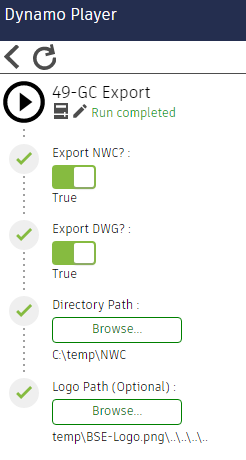
Export may take a long time, so make sure your RVT is saved before running the graph in case the Revit process needs to be killed to save time.
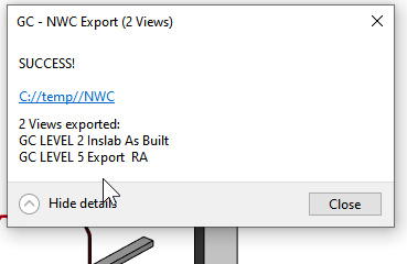
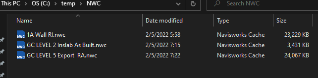
NB: A Navisworks NWC Export Utility needs to be installed from https://www.autodesk.com/products/navisworks/3d-viewers for the graph to work.
Download Navisworks NWC File Export Utility
NWC format is also useful for online viewing with Autodesk viewers:

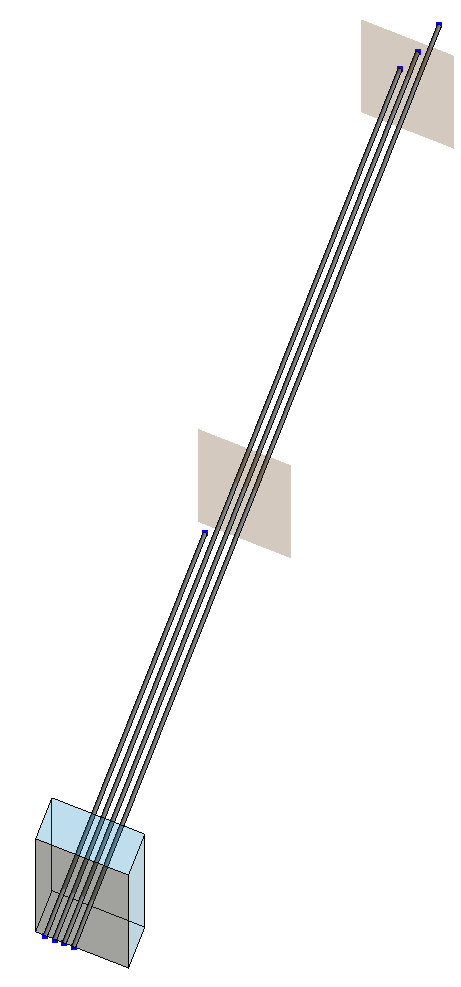
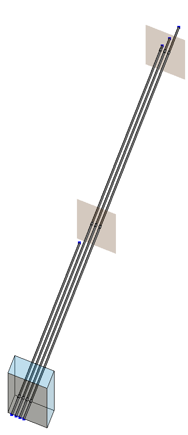
By picking a cutting plane, slice multiple conduit by a repeated distance.
Export Wire Pull Schedule
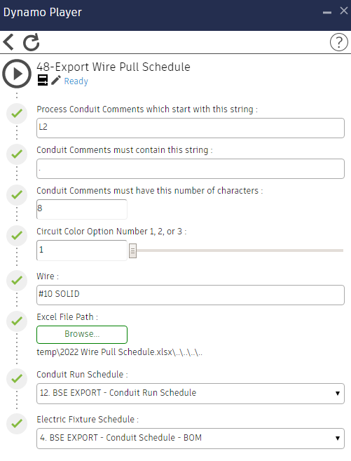
Takes data from two schedules, attempts to find intersections between Conduit and Jboxes, and makes an Excel spreadsheet.
Inputs:
Make a blank spreadsheet in Excel for the initial Excel File Path input.
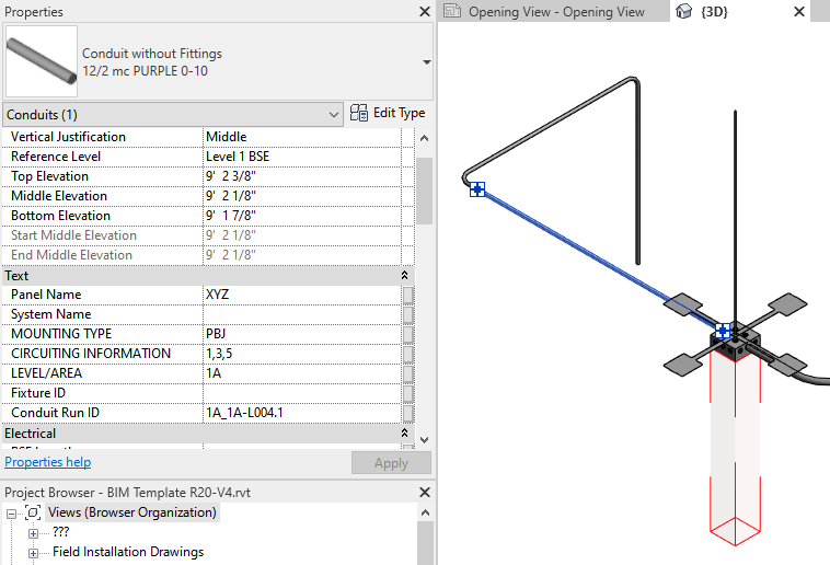
Circuiting colors are assigned by 3 options set in the Circuit Color Option Number input slider (1, 2, or 3) E.G.:


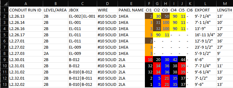
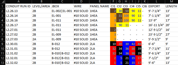
An “H” in the PANEL NAME indicates that it is 277V.
The CIRCUITING INFORMATION “CI#” should be an integer between 1 and 126 or blank.
Wire is specified by an input string.
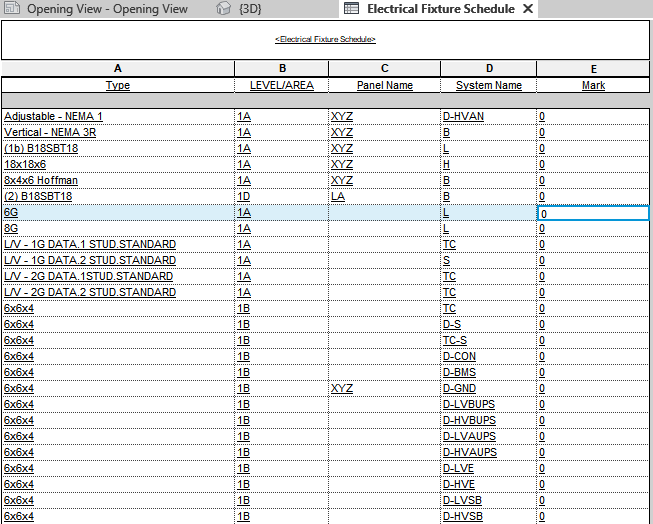
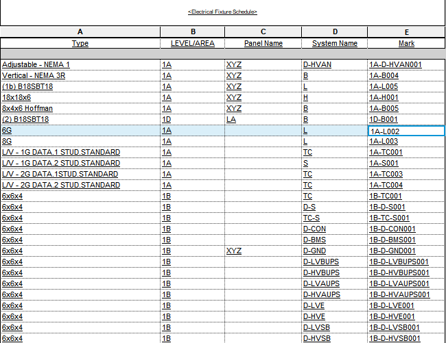
Renumber “Mark” parameter of Electrical Fixtures as the parameters “LEVEL/AREA” + “-” + “System Name” + ###
Elements are selected by filtering though dialog boxes.
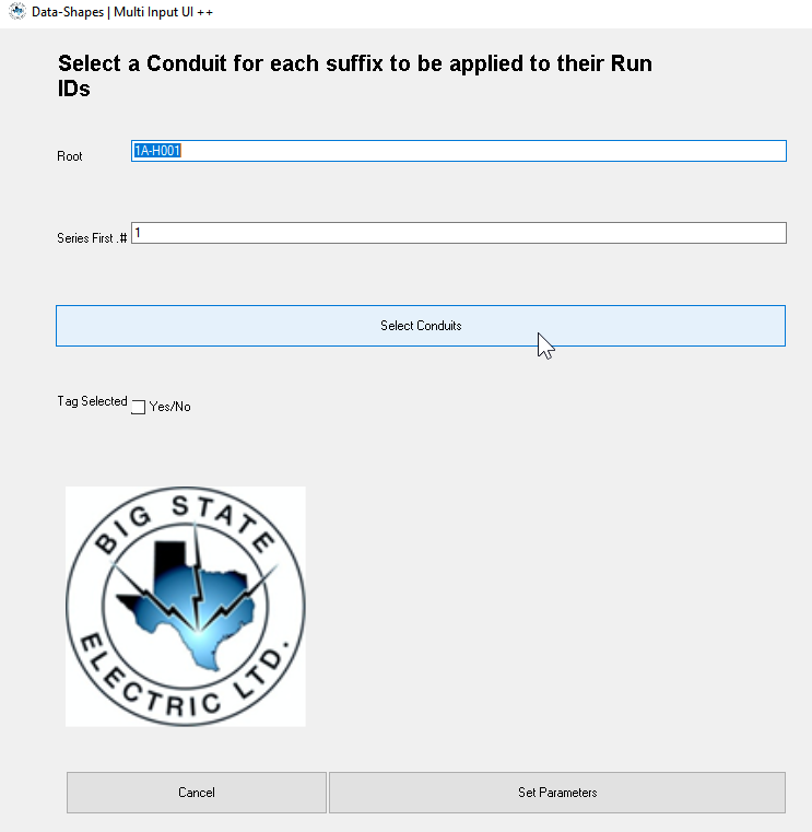
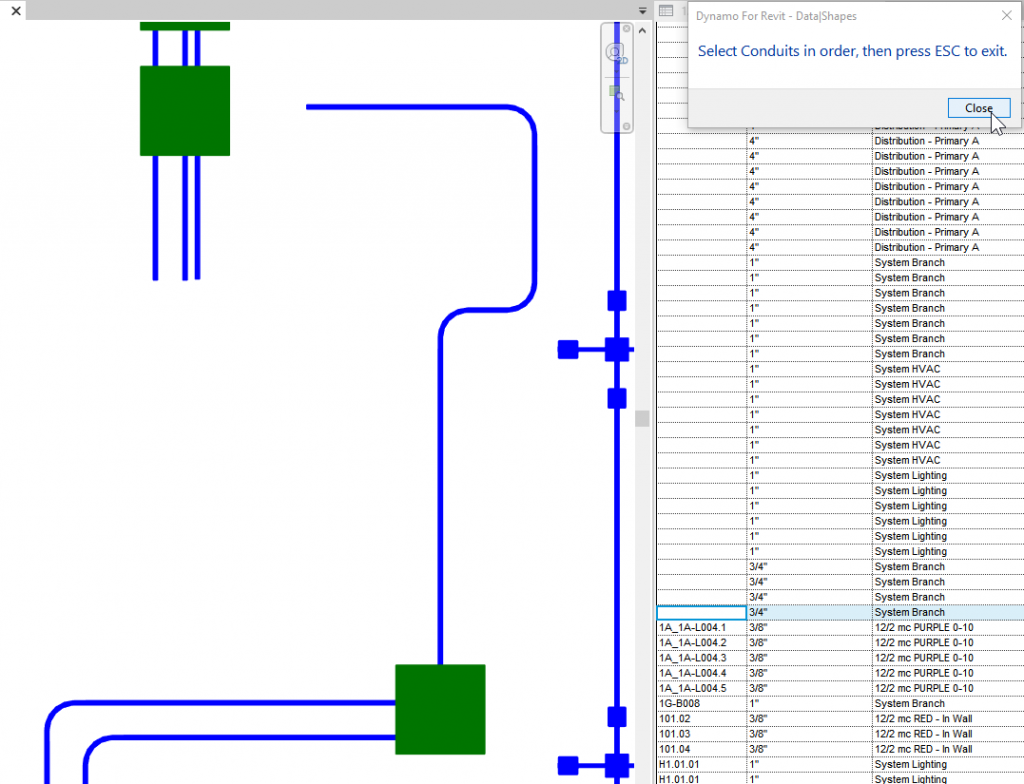
Set Conduit Run ID sequence by selecting an Electrical Fixture to extract its Mark, then selecting conduits to set their Comments to the Mark value plus a series. It also sets the Comments of all the elements in each Conduit Run. Tagging the selected Conduits is optional.

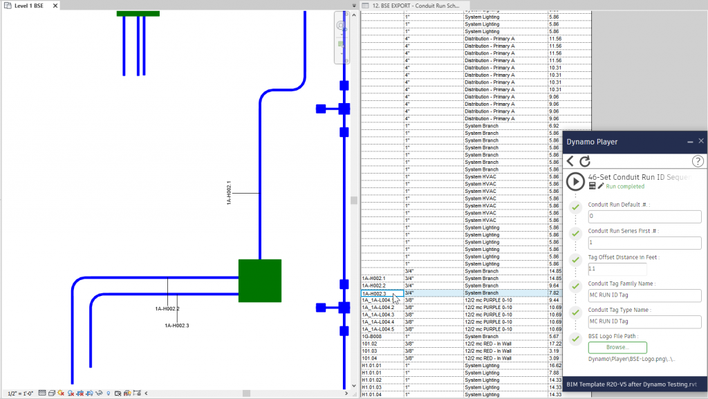
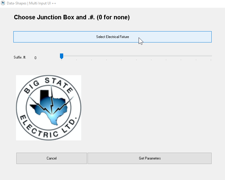
Known Issue: If single Conduit (no connected fittings) are selected, there may be some instability setting Parameters.
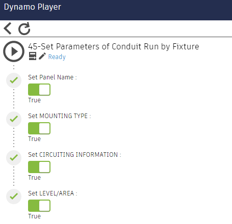
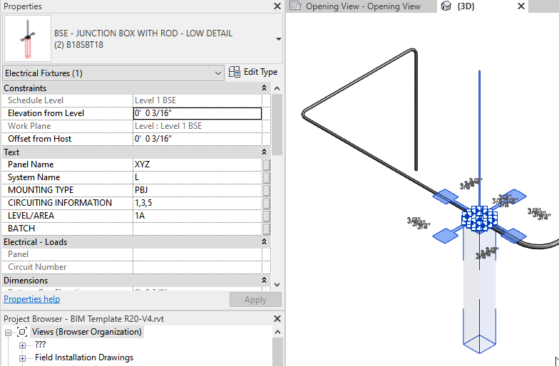
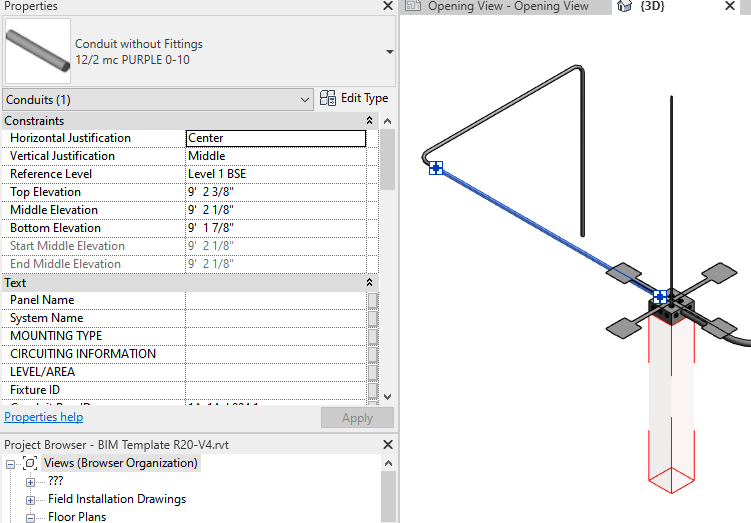
Select Conduits, Conduit Fittings, and an Electrical Fixture.
The graph will take these parameters from the Electrical Fixture and apply the values to the selected Conduits & Conduit Fittings